Scanning Tunneling Microscopy (STM)

A collection of online tools for STMing

Open Source Code: Github

*(If you find any errors in the code, please let me know on Github)

Related Topics


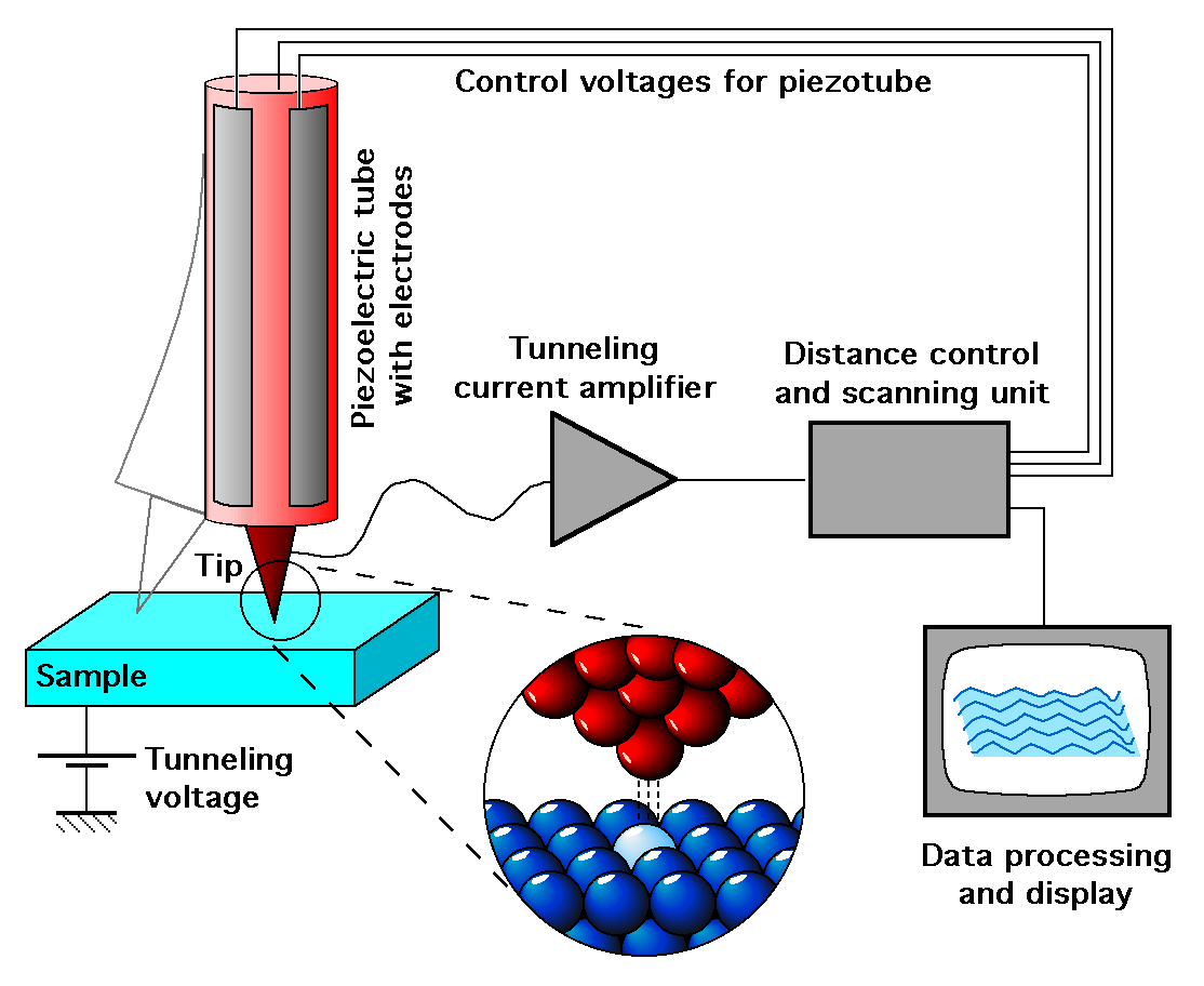
The basic example to understand the tunneling phenomenon is the free particle and the potential barrier of height Uo and width L, where the energy particle E < Uo .
The wavefunctions for the 3 regions are: \begin{equation} \psi_I(z) = e^{ik_1x}+re^{-ik_1x} \ \ ,\ \ k_1=\sqrt{\frac{2 m_e E}{\hbar^2}} \end{equation} \begin{equation} \psi_{II}(z) = Ae^{ik_2x}+Be^{-ik_2x} \ \ ,\ \ k_2=\sqrt{\frac{2 m_e (Uo-E)}{\hbar^2}} \end{equation} \begin{equation} \psi_{III}(z) = te^{ik_3x} \ \ ,\ \ k_3=k_1=\sqrt{\frac{2 m_e E}{\hbar^2}} \end{equation}

Solving for t gives: \begin{equation} t =\frac{2k_1k_2e^{-ik_1L}}{2k_1k_2cos(k_2L)-i(k_1^2+k_2^2)sin(k_2L)} \end{equation} which means a transmissivity of: \begin{equation} T = /t/^2 = \frac{1}{1+\frac{1}{4}(\frac{k_1}{k_2}-\frac{k_2}{k_1})^2 \sin^2(k_2L)} \end{equation} The Transmission coeffcient is also given by?: \begin{equation} T = e^{-2 \alpha z} \ \ ,\ \ where \ \ \alpha=\sqrt{\frac{2 m_e (U_0-E)}{\hbar^2}} \end{equation}


Transmission coefficient:

The basic example to understand the tunneling phenomenon is the free particle and the potential barrier of height Uo and width L, where the energy particle E < Uo .
The wavefunctions for the 3 regions are: \begin{equation} \psi_I(z) = e^{ik_1x}+re^{-ik_1x} \ \ ,\ \ k_1=\sqrt{\frac{2 m_e E}{\hbar^2}} \end{equation}

Feedback Loop

Using Ref. \cite{optimalConditionsForSTMTheory} we can describe the STM feedback loop as
The parameter $\alpha$ is defined as: \begin{equation} \alpha= 1.025 K_L log_{10}(e) \sqrt{\phi} \end{equation} where $K_L$ is the conversion factor of the logarithmic amplifier (in fl_K1s), and $\phi$ the average barrier height (in eV). The total gain of the closed loop can be defined as \begin{equation} G_0=\alpha A \gamma_0 G_1 \end{equation} where $\gamma_0$ is the voltage sensitivity constant. We can define the following adimensional terms: \begin{equation} G= G_0 G_2 \end{equation} \begin{equation} K= \frac{G_0 K_1}{\omega_s} \end{equation} \begin{equation} \tau_s= \omega_s \tau \end{equation} \begin{equation} W_0= \frac{\omega_0}{\omega_s} \end{equation} According to \cite{optimalConditionsForSTMTheory} (https://doi.org/10.1063/1.1149191), the stability condition is \begin{equation} K< W_0^2 \tau_s(1-G) \end{equation} the amplitude conditions are \begin{equation} K \geq \sqrt{\frac{G^2-(1+\Delta)^2 (1-G)^2}{(1+\Delta)^2-1}} \ \ \ \mbox{for}\Delta>0 \end{equation} \begin{equation} K \geq \sqrt{\frac{-G^2+(1+\Delta)^2 (1-G)^2}{(1+\Delta)^2-1}} \ \ \ \mbox{for}\Delta < 0 \end{equation} the phase shift condition can be obtained from \begin{equation} \tan{\phi_s}=\frac{K}{G(1-G)-K^2} \end{equation} which means... \begin{equation} K=\frac{-1}{2 \tan{\phi_s}} \pm \sqrt{\frac{1}{4 \tan{\phi_s}^2}+G(1-G)} \end{equation}
The optimal area for imaging is shown in the following plot as a shadowed area, constrained by the combination of limits described above


*The limits for the amplitude condition below are not the same as the ones shown in the plot above, still need to find why !


$\alpha$=

$\beta (\omega)$=

$G_0$=

$G$=

$K$=

$w_0$=

$w_s$=

$tau_s$=

$W_0$=

The parameter $\beta$ is given by \begin{equation} \beta(\omega)= \left( \frac{K_1}{i \omega} - G_2 \right) \left[ \frac{\omega_c}{\omega_c + i \omega} \right] \end{equation} where $K_1$ is the integration constant, $\omega_c$ is the cutoff frequency (rad/s) of the low pass filter, and $G_2$ is the gain of the amplifier. For the piezoelectric element that controls the vertical tip position in the STM case can be modeled by \begin{equation} \gamma(\omega)=\gamma_0 R(\omega) \end{equation} where $R(\omega)$ is the frequency dependent part of the piezoelectric element and $\gamma_0$ the voltage sensitivity constant ($\AA /V$). And $R(\omega)$ considering two poles for instabilities can be described as \begin{equation} R(\omega)=\frac{1}{1+i \omega \tau - (\omega^2 /\omega_0^2)} \end{equation} where $\omega_0$ is the resonant frequency of the piezoelectric.

Current to Voltage Amplifier (PreAmp)

\begin{equation} f_{corner}= \frac{1}{2 \pi R_{FB} C_{stray}} \end{equation} \begin{equation} V_{out}= - I_{in} \frac{R_{FB}}{\sqrt{1+(w R_{FB} C_{stray})^2}} \end{equation} \begin{equation} I_{noise}= \sqrt{\frac{4 K_B T f_{corner}}{R_{FB} }} \end{equation}


Corner Frequency (Bandwidth) :

Gain (AC) :

Johnson Noise ($I_{noise}$) :